
Service Difficulty Reports about fixed wing that either show a trend or should be known by the airworthiness community.
On this page
- DASSAULT
- DE HAVILLAND
- DIAMOND
- DORNIER
- DOUGLAS
- EMBRAER
- FAIRCHILD
- LEARJET
- MHI RJ AVIATION
- PIAGGIO
- PILATUS
- PIPER
- SAAB
Make A to C
DASSAULT
FALCON 7X/8X - Thrust Reverser Lower S-hook Bolt Loose/Disengaged
SDR #: 20201204028
Subject:
During a scheduled inspection, the bolt part number NAS6303A7 that secures the lower thrust reverser hook to the actuator was found loose. The bolt is installed up into an anchor nut with the head down and it can fall out, causing ineffective lower thrust reverser locking. The service centre personnel reported that they believe the grip length of the bolt, specified in the Illustrated Parts Catalogue (IPC), is too short and when correctly torqued, the bolt is not in safety (i.e., nut plate, 1-3 threads). The service centre personnel advised that this is the fourth aircraft that they have inspected and found with this bolt loose, and they are aware of at least one in-service aircraft where the bolt fell out. They have reported this issue to the Federal Aviation Administration (FAA) and Dassault.
Transport Canada Comments:
Following this event in February 2021, Dassault issued Falcon Service Advisory (FSA) FSA-78-30-032-R00-A – Thrust Reverser S-hook bolt loose. The FSA noted the following, “On the Falcon 7X/8X thrust reverser, there have been instances of the bolt installed on the lower S-hook being found loose or disengaged. A Dassault Service Bulletin is under development to replace the bolt with one of a longer grip length, for both the upper and the lower S-hook locations.” The FSA also noted that pending the service bulletin’s release, if a loose bolt is found during a check of the thrust reverser S-hook, refer to Safran Service Instruction SIF7X-209 Revision A for re-torquing of the bolt.
On 26 March 2021, Dassault Service Bulletin (SB) 7X-574 was issued, applicable to all Falcon 7X and 8X aircraft, to replace the existing screw with one of a longer grip length. This SB recommends incorporating the bolt replacement modification at the first opportunity and no later than at the next 12 months or 800 flight hour inspection. Transport Canada Civil Aviation expects that all operators are aware of this SB and have completed or are planning to incorporate this modification.

Figure 1: Location and access to affected area

Figure 2: Lower forward bolt head as seen through the panel

Figure 3: Back of bolt view of anchor nut shown in a mirror

Figure 4: Mirror close-up view of anchor nut shows bolt not in safety

Figure 5: Illustrated Parts Catalogue figure
FALCON 900EX - Falcon 900 - Main Wheel Found Missing After Landing
SDR #: 20170815003
Subject:
Minor edits have been made to the text below taken from the Service Difficulty Report’s Problem Description. Transport Canada Civil Aviation reserves the right to edit for spelling, grammar and punctuation to increase comprehension.
The aircraft landed uneventfully but the crew reported a significant loss of braking action. During the crew walk around after landing, the right outboard main wheel assembly was noticed to be missing. The missing wheel assembly was subsequently found at the departure airport and is being returned to the operator’s maintenance base for further evaluation. The crew said they did not see any other damage.
The initial findings by maintenance personnel noted that all of the attaching hardware and locking devices were still in place. It appears that the outer bearing disintegrated and the wheel bearing cup diameter is sufficiently large enough that the wheel can pass over the retaining hardware. The aircraft manufacturer has been advised and the affected main gear assembly is being replaced by a manufacturer’s repair team.
Transport Canada Comments:
The event was investigated and concluded that it resulted from an outboard bearing cone failure. The parts were sent for investigation but due to the high level of damage of the outboard bearing cone, it was impossible to isolate one specific root cause.
The most probable causes are improper tightening of the wheel to axle nut (under-torqueing), or improper inspection of the condition of the bearings during the last wheel installation (140 Flight Cycles (FC) before the event). The inboard bearing cone was found normally lubricated, so a lack of bearing grease in the outboard bearing cone is not suspected.
Transport Canada wants to remind all operators that installation of aircraft wheels must be performed strictly in accordance with the Aircraft Maintenance Manual’s (AMM) instructions.

Fig 1: Axle showing bearings still there and wheel missing

Fig 2: Wheel after being found

Fig 3: Inside of wheel showing residual materials from broken bearing. Note the different sizes of bearing races with larger diameter inner bearing.
DE HAVILLAND
DHC 8 301 - Failed Aileron Pulley Bearing
SDR #: 20181019011
Subject:
Minor edits have been made to the text below taken from the Service Difficulty Report’s Problem Description. Transport Canada Civil Aviation reserves the right to edit for spelling, grammar and punctuation to increase comprehension.
During heavy maintenance check, maintenance observed that the left-hand aileron cable circuit was off a pulley in the upper fuselage centre wing area and riding on the pulley retainer bolt. Further inspection showed that the bearing and centre body of the pulley had failed, allowing the pulley to tilt on the bolt, thus creating a loosening effect and allowing enough space for the cable to come off the pulley with the cable safety keeper still in place.
Transport Canada Comments:
A cable that has jumped of the pulley could cause the flight control to deflect from the neutral position and give the first indication that something is wrong. If the cable tension is low, inspect the whole control circuit and determine what is causing the cable tension to drop. It is very easy to miss that the cable has jumped off the pulley and it could cause a flight control jam in the most severe case.

Aileron cable riding between two pulleys
DHC 8 311 - Jammed Elevator Trim
SDR #: 20181011008
Subject:
Minor edits have been made to the text below taken from the Service Difficulty Report’s Problem Description. Transport Canada Civil Aviation reserves the right to edit for spelling, grammar and punctuation to increase comprehension.
While positioned on the ground, the flight crew reported to maintenance that the elevator trim wheel was stuck. When the aircraft maintenance engineer (AME) investigated the elevator trim system, it was found to be jamming on the captain’s side of the centre pedestal in the cockpit. The screw holding the indicator needle to the lay-shaft assembly was backed out and contacting the structure. This caused the elevator trim indicator to be disengaged from the captain’s trim wheel indicator track. This discrepancy was rectified as per the Dash 8 Aircraft Maintenance Manual and Illustrated Parts Catalog.
Transport Canada Comments:
These screws are located in an area that is not accessed often and is easy to miss. Maintainers should make sure that free movement of the control levers or trim wheel is not restricted by loose parts. Also, when working in this area make sure that the screws and bolts have the correct torque when replacing parts.

Image shows the screw backed out from the lever.
DHC 6 300 - Aileron Servo Tab Control Rod Crack
SDR #: 20150312008
Subject:
Minor edits have been made to the text below taken from the Service Difficulty Report’s Problem Description. Transport Canada Civil Aviation reserves the right to edit for spelling, grammar and punctuation to increase comprehension.
During routine maintenance activities, the Aircraft Maintenance Engineer (AME) noticed a crack in the aileron servo rod. This same cracked area on the rod was also swollen. It is suspected that water accumulated inside the rod and froze. The aileron rod was replaced with no additional defects noted.
Transport Canada Comments:
The ingress of water and freezing of the Viking Air Limited (VAL) DHC-6-300 aileron servo tab control rod assembly is a known issue.
The Original Equipment Manufacturer (OEM) of the DHC-6-300 Twin Otter aircraft, DeHavilland Aircraft Company (DHC), raised awareness of the issue of water ingress and freezing of the Left-Hand (L/H) and Right-Hand (R/H) Part Number (P/N) C6CW1048-1 aileron servo control rod assemblies by issuing Service Bulletin (SB) 6/472 on January 18th 1985.
The P/N C6CW1048-1 rod assembly was constructed with a hollow tube, which could accumulate water and freeze. The freezing would expand the tube and cause it to crack. SB 6/472 was issued to introduce Modification (Mod) No. 6/1850, which called out a replacement solid tube assembly P/N C6CW1087-1.
It should also be noted that the DHC-6-300 Product Support Manual (PSM) 1-63-4 Illustrated Parts Catalogue, Chapter 27-10-00 Figure 5 – Servo Tab Installation, depicts at item 90, control rod P/N C6CW1087-27 but that is the P/N for the solid rod only, not the assembly with both rod ends installed. The complete solid rod assembly P/N C6CW1087-1 is depicted at item 35 (not illustrated). The hollow tube control rod assembly P/N C6W1048-1 (item 30) is no longer procurable (NP), nor are the older P/N DSC4-3A rod ends (item 80).
Transport Canada Civil Aviation (TCCA) recommends that DHC-6 operators and maintainers consider inspecting their fleets to see if they still have the older P/N C6CW1048-1 hollow tube control rods installed and if so, incorporating SB 6/472 due to the inherent safety benefits achieved by replacing the hollow tube rod assemblies with P/N C6CW1087-1 solid rod assemblies.

C6CW1048-1 Control Rod Assembly.
DHC 8 311 - Cracked Bleed Air Pipe Flange
SDR #: 20180913014
Subject:
Minor edits have been made to the text below taken from the Service Difficulty Report’s Problem Description. Transport Canada Civil Aviation reserves the right to edit for spelling, grammar and punctuation to increase comprehension.
There was a 27 degree engine Inter-Turbine Temperature (ITT) rise with number one bleed selected on and air cycle machine (packs) off. Suspect leak between left-hand check valve and engine shut-off valve. Found a cracked flange on the bleed air duct.
Transport Canada Comments:
Cracks on ducts can be hard to find when they are hidden under clamps. Sometimes some disassembly will be required to find the damage. Also some parts are known to fail on regular intervals which makes troubleshooting easier if the person doing the work is familiar with the aircraft model.

Cracked flange on the pipe
DHC 8 402 - Damaged Fuel Ejector Check Valve
SDR #: 20190905009
Subject:
Minor edits have been made to the text below taken from the Service Difficulty Report’s Problem Description. Transport Canada Civil Aviation reserves the right to edit for spelling, grammar and punctuation to increase comprehension.
Crew reported a #2 engine fuel press caution light during climb when turning off #2 auxiliary pump. Maintenance replaced the right-hand primary ejector pump and the aircraft returned to service. A damaged check valve was reported on the removed pump.
Transport Canada Comments:
Broken ejector pump check valves are hard to troubleshoot since disassembly is required to find the failed parts. However, this type of failure can be expected to be found on older aircraft because moving parts do wear out and require replacement when they fail.

Photo Ejector pump and damaged check valve
DHC 8 301 - Dash 8/300 Secondary Flap Drive Shaft
SDR #: 20180711016
Subject:
Minor edits have been made to the text below taken from the Service Difficulty Report’s Problem Description. Transport Canada Civil Aviation reserves the right to edit for spelling, grammar and punctuation to increase comprehension.
Flaps at 5 degrees and will not move. Flap drive caution is on. Secondary flap drive shaft (over fuselage) found seized and sheared. Drive shaft assembly removed in accordance with Aircraft Maintenance Manual 27-52-11 page 201. Coupling also found seized and bearing had failed. The complete secondary flap drive path was replaced.
Transport Canada Comments:
This drive coupling failed due to lack of lubrication. Aircraft operating environment has an impact on components that are sealed if the seals fail and let moisture in. These areas are very hard to inspect for preventive maintenance. Operators should track the reliability of these components and replace them at a predetermined interval that suits their operating environment.

Coupling without any lubrication.
CAN, DHC 8 102 - Failed Parking Brake Control Valve
SDR #: 20180226023
Subject:
Minor edits have been made to the text below taken from the Service Difficulty Report’s Problem Description. Transport Canada Civil Aviation reserves the right to edit for spelling, grammar and punctuation to increase comprehension.
During parking, when applying park brake #2, the hydraulic gauge went to zero and a large amount of hydraulic fluid was running down the right side of the aircraft. Inspection of fuselage panel 264BR revealed the brake control valve was severed. Park brake control valve was replaced with a serviceable unit, in accordance with aircraft maintenance manual chapter 32-44-16. Inspection of the failed part revealed the part failed in 2 stages, an initial crack extending around the cylinder, followed by subsequent catastrophic failure of the cylinder. The stamp on the outer cylinder of the brake valve indicates that it was originally assembled in 1Q89 (assumed to be 1st quarter 1989) and cure date of 3Q87 (assumed to be 3rd quarter 1987)
Transport Canada Comments:
This is a typical fatigue failure that started progressing slowly and then finally failed. These types of failures are hard to detect even if the part is sent for overhaul, unless nondestructive testing is used to detect the cracks before failure. If the same part keeps failing after a certain number of cycles, a recurring defect report can be used to determine the life limit of the part and remove it from service before failure.

1. End view of the valve where you can see how the crack progressed.

2. Failed valve body as found in the aircraft.
CAN, DHC 8 402 - Broken exhaust trunnion mount
SDR #: 20171010009
Subject:
Minor edits have been made to the text below taken from the Service Difficulty Report’s Problem Description. Transport Canada Civil Aviation reserves the right to edit for spelling, grammar and punctuation to increase comprehension.
During general visual inspection task DH4-000-05-410-302 of the left-hand nacelle, maintenance discovered that both trunnion mounts of the aft jet pipe assembly had broken off. Upon further investigation, both of the right-hand aft jet pipe assemblies trunnion mounts were also found broken.
Transport Canada Comments:
Once one of the mounts breaks off, the tailpipe is allowed to vibrate and can cause the other mounts to break off. Timely discovery of the damage is essential to limit the amount of damage.

Image of the tailpipe from the parts manual

Mount broken off the tailpipe

Broken mount
CAN, DHC 8 314 - Leaky fuel line
SDR #: 20171026007
Subject:
Minor edits have been made to the text below taken from the Service Difficulty Report’s Problem Description. Transport Canada Civil Aviation reserves the right to edit for spelling, grammar and punctuation to increase comprehension.
During cruise flight, the crew noticed a strong fuel smell and also noticed a leak coming from the left-hand (L/H) engine nacelle vent.
The L/H engine fuel motive flow line from the firewall to the Fuel Control Unit was found to be leaking.
Transport Canada Comments:
Most of the time, it’s impossible to detect if fluid lines are deteriorating. These fuel lines are on-condition, however, they should still be carefully inspected during inspections.

Leak in a braided fuel line
CAN, DHC 8 402 - Chafed hydraulic line
SDR # 20170918004
Subject:
The standby power unit to the reservoir hydraulic line was found with chafing damage. The line was replaced and the aircraft was subsequently released for service.
Transport Canada Comments:
When inspecting hydraulic lines, make sure that areas that are tight, or areas where lines may come in contact with other lines or structure, are protected from chafing.

Chafed line with damage almost through the wall thickness of the line.
DHC-8-402 - Cracked Brake Fitting
SDR # 20170918003
Subject:
During ground handling, a hydraulic leak was noted from the #1 nacelle. Maintenance investigation determined that both brake fuse/shuttle assemblies were leaking from the lower (parking brake) fittings. The fittings were found to be cracked perpendicular to the threads. The fuses were replaced and the aircraft was subsequently released for service.

Cracked brake fitting
DHC-8-400 - Broken Aileron Cable
SDR # 20160728018
Subject:
During the pre-flight check walk around inspection, the right hand outboard aileron was found drooping as compared to the left hand outboard aileron. While performing an inspection on the control cable, they found that one of the cables sections was broken.
The last detailed visual inspection task card 27-900-705-A01 and tension check task card 27-900-706-A01 accomplished was completed 47 flight hours previous to the event. The above tasks are scheduled to be completed at a 2500 hour interval from when the cable was installed.
The cable is part number 82742412-001. The cable was replaced and the aircraft returned to service.
Transport Canada Comments:
A reminder when inspecting cables, ensure the entire section of the cable including areas that are hard to see are inspected properly. Keep in mind that the control cable has to last safely until the area is inspected again and in this case there was an expectation for this cable to last 2500 hours before re-inspection.

Cable broken at the bellcrank
DHC-8-402 - Broken Wheel Tie Bolts
SDR # 20170523012
Subject:
Flight crew reported an under-inflated tire in position three. Maintenance found five tie bolts fractured and some others loose. Both landing gear main wheel assemblies were replaced before releasing the aircraft to service.
Transport Canada Comments:
Recently, a number of different aircraft models have reported broken main wheel tie bolts. Always deflate the tire before removing a wheel since broken tie bolts can cause the rim to separate and has been known to seriously hurt the person working on the wheel. In this case the tire had deflated on its own but that is not always the case.

Five broken tie bolts
DHC-8-402- Burnt Terminal Block
SDR # 20170116010
Subject:
During ground maintenance, the #1 engine generator feeder cables were found fused at the engine firewall terminal block. Damage to the firewall was sustained, requiring replacement of the firewall in that area.
Transport Canada Comments:
It is unknown what caused the feeder cables to short and burn the firewall, however, these images show the kind of damage that can be caused by large cables shorting and burning. On high current cables, sometimes the damage is already done by the time the protection devices trip and the power to the affected circuit is cut. Loose connections on these cables can cause overheating of the terminal blocks and should be checked for proper torque during inspections.

Damaged firewall
DHC-8-400 - In-flight Shutdown Due to Damaged Exhaust
SDR # 20160928011
Subject:
During a climb at approximately 5500ft, the fire bell sounded and the left hand engine fire indication illuminated. After reducing power, the indication extinguished at approximately 50% engine power. The crew shut the engine down without discharging the fire bottles and returned to base. All engine parameters were observed as normal prior to the fire warning.
Troubleshooting by maintenance found the left hand inner exhaust separated at the center flange due to prior removal and installation by maintenance. A new exhaust assembly was then installed.
Transport Canada Comments:
An in-flight shutdown and damage to the parts was caused by improper maintenance. It is important that maintenance personnel follow instructions published by the manufacturer and take time to inspect the work. There is no evidence that this incident was caused by human factors, however it reminds us that the person doing the work could be distracted, fatigued or pressured to get the work done.
Transport Canada Civil Aviation (TCCA) recommends having someone inspect your work before close up in order to minimize the risk of faulty workmanship.

Damaged exhaust duct flange
DHC-8-300 - Corroded Wires
SDR # 20160928023
Subject:
During a daily inspection, maintenance found the #2 mechanical fuel control circuit breaker (H10) was popped and could not be reset. After extensive troubleshooting, the right hand wing root cannon plug (9811-P14) was found badly corroded. Cable assembly part number 82445042-313 was replaced. Aircraft was returned to service.
Transport Canada Comments:
The operator inspected other aircraft in the fleet and found the identical cannon plug corroded on the left and right side wing root of other aircraft. These cannon plugs are covered by heat shrink, which by orientation of the wiring harness, is letting humidity penetrate the wiring harness. Trapped humidity seems to be the cause of the corrosion.
In order to reduce the number of recurring defects, operators should adjust their maintenance schedules when they find issues that may be caused by the environment they operate in.

Corroded cannon plug
DHC-8-402 - Disintegration of Starter-generator Drive Shaft Dampener Plate
SDR # 20160408013
Subject:
While completing a walk around during a service check, it was noted that the #2 engine starter-generator had a lot of rust/material coming from the cooling exhaust port onto the cowling. The starter-generator cooling fan/shaft was discovered loose. Further investigation was required.
Maintenance removed and replaced the right hand starter-generator and the starter-generator drive seal with a serviceable unit as per the aircraft maintenance manual (AMM). A check revealed that the right hand starter- generator was serviceable. It appears that the source of the rust colored material is from the complete disintegration of the shaft dampener plate friction ring, part number 150SG1070, located in the Honeywell component maintenance manual chapter 24-31-01 item 120.
Transport Canada Comments:
Due to high starter-generator loads, operators should consider adjusting appropriate component overhaul intervals based on reliability data to prevent failures between overhaul intervals.

Starter-generator damaged shaft dampener
Canada, DHC-8-311 - Failed Elevator Spring Tab Bearings
SDR # 20161129010
Subject:
The aircraft required excessive nose up trim on take-off and was difficult to trim in cruise. The autopilot oscillated in Altitude/Vertical Navigation (alt/vnav) mode. The aircraft felt nose heavy and unusually sensitive to pitch trim input.
Maintenance found:
- left hand and right hand spring tab tube end bearings and spigot severely worn
- left hand spring tab tube input link bearing worn
- right hand elevator to airframe bearings found worn
All worn parts were replaced with new parts as per the Dash 8-300 aircraft maintenance manual.
Transport Canada Comments:
Proper inspection techniques should be able to identify these worn parts during scheduled inspections before they fail in service. Access to the area where these parts are located requires a man lift or a work stand because the aircraft has a T-tail and makes it harder for maintenance staff to work in the area. Availability of proper equipment is important to ensure that the inspection tasks can be properly completed.

Worn and damaged spigot

Completely destroyed bearing.
DIAMOND
DA 20 A1 - Rudder Pedal Frame Assembly Lower Mount Failure
SDR #: 20231030030
Subject:
As we can see on the pictures, the rudder pedal frame assembly (item number 15) in the Illustrated Parts Catalogue (IPC), part number 22-2729-60-00, failed. The lower mounting hole broke off which causes the connecting rod of the brake cylinders to become loose. A pilot reported that the rudder pedals become "stuck sometimes".
Transport Canada Comments:
Upon further inspection, both mounting hole ears have fractured. DA20-A1 and DA20-C1 share a similar design, although this failure mode has not been reported in the past. It is important to recognize that higher time aircraft may require special attention to areas that undergo stress on a regular basis, particularly flight control systems. Owners, operators and maintainers are reminded to submit a Service Difficulty Report if any similar defects are found.
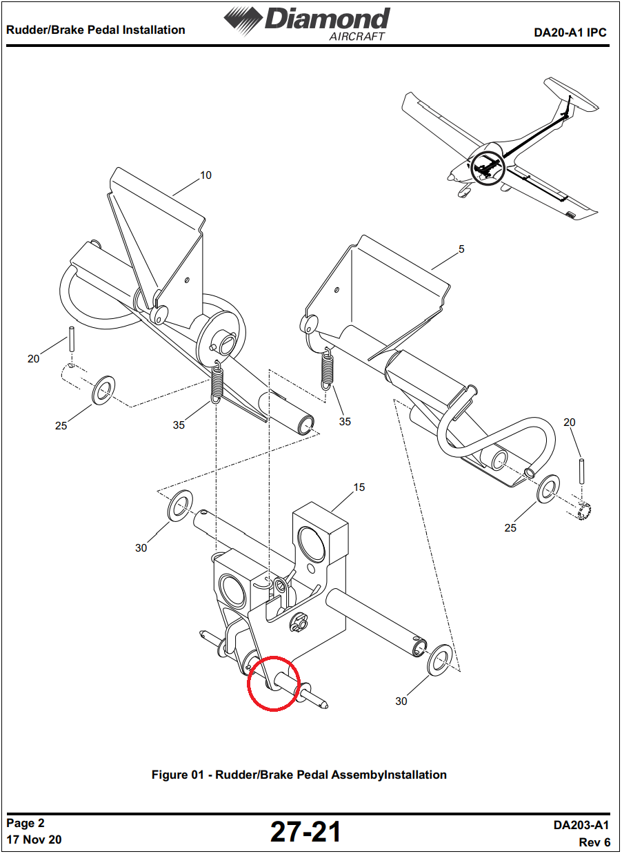
Figure 1 – (IPC) showing location
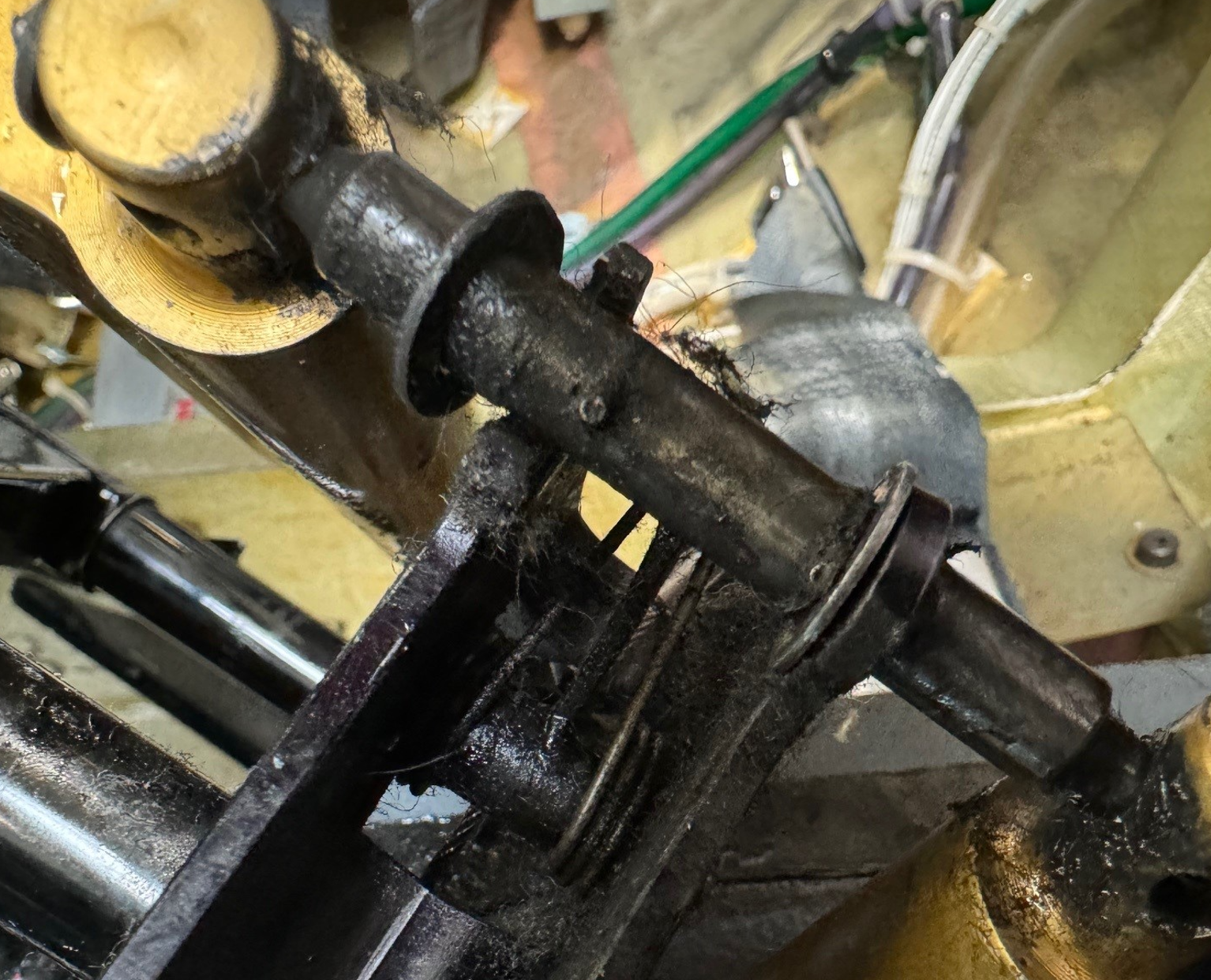
Figure 2 – Fractured mount hole
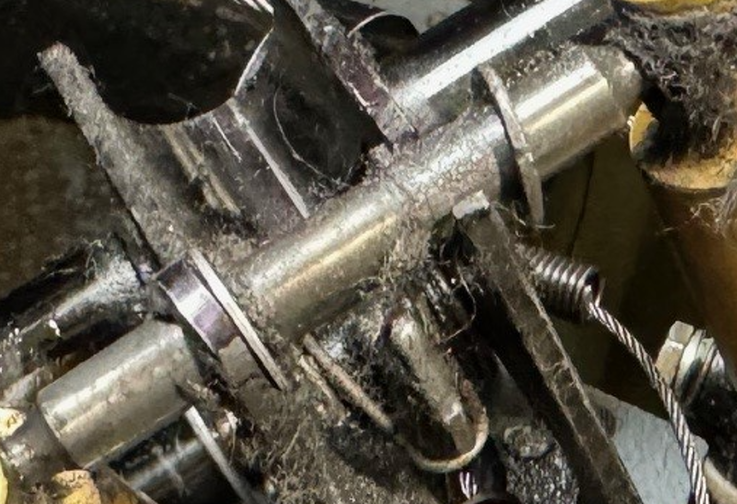
Figure 3 – Fracture of both mount holes
DA 20 C1 - Elevator Control Horn Attachment Bolt – Worn Through Lower Skin
SDR #: 20220318008
Subject:
During the performance of a 300-hour inspection, the forward elevator control horn attachment bolt was found worn through the lower skin of the elevator.
Transport Canada Comments:
The root cause of this failure is not entirely clear. Incorrect torque during the installation of the control horn bolt, and/or horizontal stabilizer water drain hole obstruction in combination with freeze/thaw cycles may have contributed to this failure. Maintainers are reminded to refer to the appropriate fastener installation torque values. In cases where specific torque values are not defined, standard torque values should be referenced.
. Elevator control horn as installed on elevator.")
Figure 1 – View of removed elevator (upside down). Elevator control horn as installed on elevator.
. Forward attachment bolt worn through lower skin.")
Figure 2 – View of removed elevator (upside down). Forward attachment bolt worn through lower skin.
DA 40 NG - Engine Power Loss Due to Induction Coupling Disconnect
SDR #: 20191023011
Subject:
It was reported that the aircraft experienced a power loss during take-off. The pilot force landed the aircraft into a field, passed through a ditch and came to rest with nose landing gear damage and structural damage to the aircraft. On inspection, the connection between the intake manifold charge air hose and charge air duct assembly was separated. No other defects noted.
Transport Canada Comments:
Incorrect installation of worm drive clamps in the induction system can lead to engine power loss. Owners, operators and maintainers are reminded to be aware of the most current instructions for continued airworthiness (ICA) available for their specific product.
Service Information Letter SI 40NG-007 dated 10 May 2011 was issued by Diamond Aircraft Industries GmbH informing customers on the installation of worm drive clamps. The information in this letter has since been incorporated into the DA 40 NG’s maintenance manual. See document number 6.02.15 Revision 3, section 20-70-00.
Temporary Revision AMM-TR-MÄM 40-901 dated 9 November 2017 was issued and includes the following:
“Worm drive clamps are for single use only. Replace clamp with a new clamp every time the clamp is loosened or removed. Secure each worm drive clamp with safety wire once they are installed and tightened to the appropriate torque (see Paragraph D. Tightening Torques for Worm Drive Clamps).
Caution: Reuse of worm drive clamps can lead to a failure of the clamps and may cause loss of engine power.”
AS, DA 42 - Engine Failure due to Crossed Fuel Lines
SDR #: 20200609020
Subject:
ECU (Engine Control Unit) A FAIL and ECU B FAIL indications displayed during flight. Maintenance personnel discovered that the fuel supply line and the return fuel lines were found crossed (engine drawing fuel from return fitting) at the right wing root attach point connections. The lines are the same size and can be easily mixed up when being reattached following wing removal.
Transport Canada Comments:
This incident occurred during flight with an engine failure. Unfortunately, the error wasn’t discovered during post-maintenance ground runs.
It is possible to mix up the fuel supply line and return fuel line connections on both left-hand and right-hand wing root connection points, although the part numbers are unique. This is also possible on DA 40 D and DA 40 NG model aeroplanes. Transport Canada Civil Aviation reminds maintenance personnel of the importance of labeling hoses / fittings during disassembly.

Fuel supply and return line fittings
DORNIER
328 100 - Ballast Fire Creates Exciting Flight
SDR #: 20190121014
Subject:
Minor edits have been made to the text below taken from the Service Difficulty Report’s Problem Description. Transport Canada Civil Aviation reserves the right to edit for spelling, grammar and punctuation to increase comprehension.
An indication of a cargo fire was reported and a tactile search was performed. The captain advised that they would go through their checklist and may have to declare an emergency. The pilot was then informed of the fire extinguisher going off, he declared an emergency and asked if there was smoke in the cabin, to which the flight attendant confirmed that there was no smoke or fire. The pilot advised that he would conduct a normal landing and wait for fire crews. Maintenance found the ballast smelt, and when it was removed, it showed internal signs of a short and had an intense smell of electrical burn.
Transport Canada Comments:
The quick reaction and persistent approach the flight attendant took in this case prevented what could have been a very different outcome. It can sometimes be difficult to pinpoint the source of electrical fires/smoke like in this case. Often, electrical components are buried behind sidewalls or under floor. During routine maintenance, a thorough inspection of these components could prevent inflight emergencies.

1. Internal view of Emergency Light Ballast. Notice the charred internal components

2. Scorching and heat residue on the inside surface of the Ballast cover.
DOUGLAS
DC3C - Attentive Walk Around Prevents Possible Incident
SDR #: 20170614007 and 20171127017
Subject:
During two separate incidents, an operator of the DC3C with the Basler turbo prop conversion has found cracked outboard elevator attachment hinge fittings. The first incident occurred during a pilot pre-flight walk around. The pilot was checking for free play at the left-hand elevator and noted a clunking sound while shaking the elevator. Further investigation found that the left-hand outboard elevator attachment hinge horn was broken at the bolt attachment.
The second incident occurred during a 150-hour inspection. A close visual inspection of the elevator attachment hinge fitting, located on the right-hand outboard stabilizer location, showed signs of cracked paint. The AME further examined the area closely with a borescope and detected a crack. The crack was not visually detectable without the aid of magnification, such as a borescope, due to the limited access while the elevator is installed.
In both cases, the elevator attachment hinge was replaced with a serviceable part and the aircraft returned to service.
Transport Canada Comments:
Had it not been for an attentive pilot performing the usual pre-flight walk around or an eager AME performing the same old 150-hour inspection, these snag may have gone unnoticed. Remember the dirty dozen and avoid complacency.
“Today is the day I will find something!”

Hinge with missing piece

Close up, borescope view of hinge end with crack

Ground view of outboard Elevator Hinge
EMBRAER
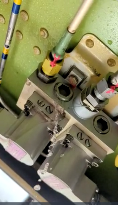
EMB 545 - Leaky Brake Control Valve
SDR #: 20230410034
Subject:
The crew contacted maintenance for a (blue advisory) hydraulic #1 low quantity crew alerting system (CAS) in flight. The decision was made to divert the aircraft and land. No caution CAS message appeared during the event. Hydraulic system #1 quantity started at about 51% and dropped to 16% after touchdown. The attached picture shows the brake control valve, part number 90007135-2, with an Allen key bolt backed out and leaking hydraulic fluid. A picture of the correctly installed Allen key bolts on a serviceable brake control valve is attached for reference.
Transport Canada Comments:
This interesting event shows how a component can fail for many reasons. Control valves will typically fail mechanically or electrically. The backing out of a set screw shows a possible assembly error at overhaul or manufacture.
Maintainers and operators are asked to watch for even the less apparent faults.
Picture 1 – Leaking Brake Control Valve
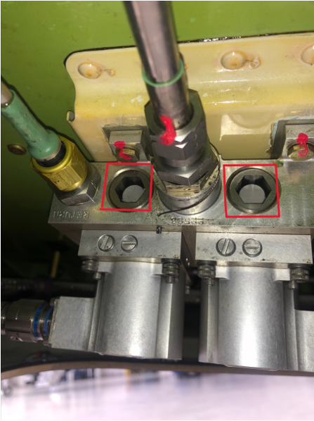
Picture 2 – New Brake Control Valve with flush set screws
FAIRCHILD
SA227AC - Air Conditioning Cooling Turbine Failure
SDR #: 20201007004
Subject:
On short final, a burning smell was noticed. After landing, on the short taxi to the ramp, smoke was noticed in the cockpit. On arrival at the ramp, the smoke had increased, the engines were shut down and the aircraft flight crew vacated more expeditiously than normal (this is a freight aircraft, no passengers were on board, two (2) crew only). The smoke cleared and no evidence of a fire was found anywhere in the aircraft. Maintenance investigation found that the left-hand (L/H) conditioned air-cooling turbine had failed and that the turbine bearing had overheated and failed, which caused the oil reserve in the turbine to smoke and enter the cabin air vent system. The turbine is an on-condition item that is subject to a 200-hour oil level check during which a visual inspection is also carried out. This inspection was carried out 172 hours prior to the failure, with no abnormalities found.
Transport Canada Comments:
Cooling turbine bearing failure often results in seizure, and multiple service difficulty reports (SDRs) suggest that this is accompanied by smoke/oil mist in the cabin. Other indications of failure have been described as: smoky haze, white smoke, or acrid smell in the cabin/cockpit. Cabin temperature rising, while not responding to temperature controller or manual temperature control, has also been reported.
It is important to reiterate that inspection and servicing outlined by the manufacturer should be completed correctly and during the suggested interval. In addition, SDR data suggests that high oil level, or a blockage in the air delivery system may contribute to cooling turbine failure.
Australian Transport Safety Bureau (ATSB) covered a similar occurrence: AB-2018-033. The following picture from this report illustrates the result of a typical cooling turbine bearing failure.

Picture 1 – Cooling turbine bearing failure
LEARJET
45 - Environmental Control System (ECS) Muffler Cracked
SDR #: 20220829024
Subject:
During routine maintenance, insulation was found blown into the hydraulic access panel and filter areas. Further investigation revealed that the cockpit ECS muffler assembly had cracked in two places (one crack was 2 1/8" long and the other was 3 1/8" long). No issues were noted in flight prior to the finding. This muffler was installed in 2000, in accordance with Service Bulletin 45-21-4 Modification of the Environmental Control System for Reduced Cabin Noise Levels and had accumulated 8178.0 hours since installation. The muffler was removed, inspected, and re-installed in 2020 due to other fleet muffler issues with no defects noted at that time.
Transport Canada Comments:
Additional reports of failure have been discovered after experiencing ECS anomalies in flight. Low airflow to the cockpit, inability to maintain selected heat settings and reports of cabin pressurization loss have been described by flight crews.
Learjet has noted that adequate cabin pressurization is available regardless of a rupture in the muffler assembly. It may cause the cabin air not to be routed through the operator’s desired duct locations, but it will still reach the cabin, and with additional ECS ducting through the bulkhead, safe cabin pressure levels will be maintained.
This area is routinely accessed during a 300 hour hydraulic filter replacement. Damaged or loose outer insulation wrapping around the muffler or insulation material located near the hydraulic manifold is a good indication that the cockpit ECS muffler may be cracked.

Picture 1 – Muffler as installed, adjacent to the hydraulic filter manifold, outer insulation wrapping damage is evident

Picture 2 – Muffler outer wrapping removed, cracked at upper weld seam
45 - Loss of Hydraulic Fluid Can Lead to Complete Hydraulic Failure
SDR #: 20180914008
Subject:
Minor edits have been made to the text below taken from the Service Difficulty Report’s Problem Description. Transport Canada Civil Aviation reserves the right to edit for spelling, grammar and punctuation to increase comprehension.
Aircraft was in the Climb Out when the crew received Engine Indicating and Crew Alerting System (EICAS) messages: MAIN HYD QTY LOW, MAIN HYD PRESS, and LH HYD PUMP.
Hydraulic pressure had dropped to 100-150 Pounds per Square Inch (PSI) with the Left-Hand (LH) pump flashing amber on the hydraulic synoptic page. The crew declared an Emergency and returned to the airport for an uneventful landing. Maintenance found the LH main low pressure switch S9 connector body to have bulged and failed, causing a large leak and subsequent loss of fluid.
Transport Canada Comments:
Loss of hydraulic fluid can lead to complete hydraulic failure. Main and Auxiliary Hydraulic systems share the same reservoir, loss of fluid may render both unserviceable. As well, cavitation can damage hydraulic pumps which can be very costly. Learjet Service Bulletin (SB) 45-29-17 was issued in 2010 and is currently at revision 2. The SB subject matter recommends replacing low pressure switches in the main, auxiliary and spoiler systems. Transport Canada Civil Aviation (TCCA) recommends that operators follow the manufacturer’s recommended Service Bulletins.

Pic#1 – Low pressure switch S9 leak

Pic#2 - Bulge in connector body and subsequent protruding O-ring
MHI RJ AVIATION
CL600 2C10 (RJ700) - RJ700 – Fuselage Skin Damage Due to Electrical Arcing
SDR #: 20210210012
Subject:
Ground power (115V AC) arcing caused burn damage to the fuselage skin panel near the Air Driven Generator panel and was located between stringers 22R and 23R, 1.5 inches aft of FS.193.00. The fuselage skin damage was caused by an electrical arcing heat and measures 1.5 inches wide by 2.0 inches long, with the skin protruding out by 0.008 inches. Additional damage was found in the external power box inside the fuselage, which has a 3.0-inch-by-1.5-inch burn hole.
Transport Canada Comments:
The cause of the arcing damage is not currently known. The damage is quite significant and is in an inspectable area, therefore TCCA would like to highlight this service difficulty report to promote industry awareness.
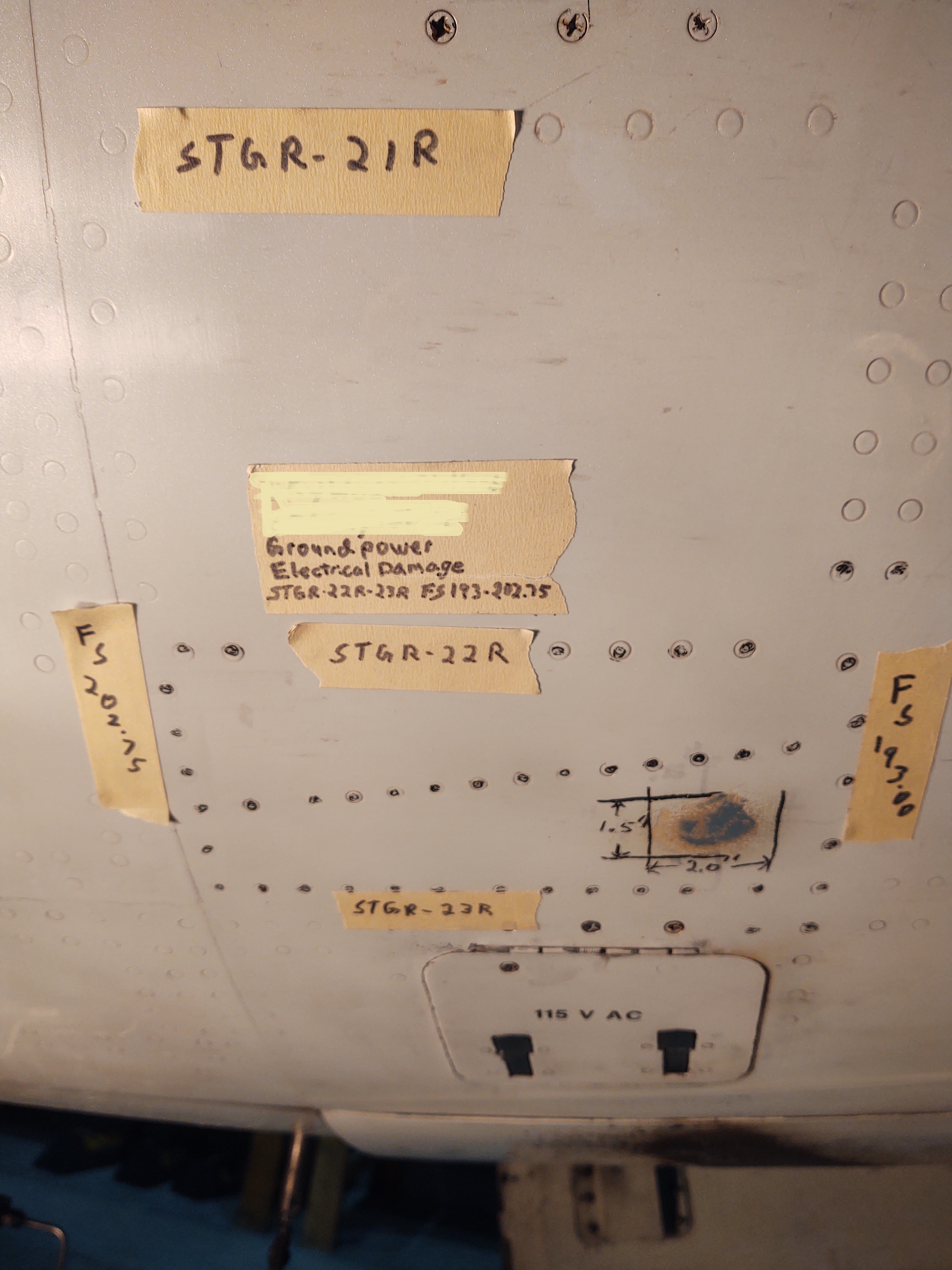
Figure 1 – External view of damaged area

Figure 2 – External close up

Figure 3 – Internal damage
CL600 2D24 (RJ900) - CRJ 900 – Passenger Door Aft Fitting Cracks and Fitting Attachment Bolts Sheared
SDR #: 20200117004, 2020117007, 20201218008, 2020117010, 2020117012, 2020117022
Subject:
While working on the passenger door, maintenance personnel observed that one of the four bolts which secures the upper aft latch fitting was sheared and the latch fitting had a crack in the radius. The broken bolt was removed, a new bolt was installed, and the cracked fitting was replaced. The aircraft times in service were 44329 hours and 22558 flight cycles.
On a second aircraft in the same operator’s fleet, while working on the passenger door, maintenance personnel observed that one of the four bolts which secures the upper aft latch fitting was sheared. The broken bolt was replaced. The maintenance personnel also discovered the fitting in the upper aft door structure was cracked in the radius, so the fitting was replaced. The aircraft times in service were 44113 hours and 22761 flight cycles.
On a third aircraft in the same operator’s fleet, while removing access panels on passenger door assembly during the aircraft maintenance heavy check visit, a crack was observed on the upper outer internal frame fitting. Further inspection also revealed one of the fitting attachment bolts was sheared. The broken bolt was removed, a new bolt was installed, and the cracked fitting was replaced. The aircraft times in service were 46309 hours and 23868 flight cycles.
Transport Canada Comments:
As highlighted in previous Feedback articles, this area of the passenger door is prone to water ingress and corrosion which can lead to cracked and broken bolts. In this case, along with broken bolts the operator found cracks in the door fittings.
These, as well as previously reported corrosion and bolt breakage events have been assessed by the design approval holder and determined to pose minimal safety risk provided the recommended inspections and standard aircraft maintenance practices are respected. The area is the subject of a lengthy inspection interval and the maintenance instructions do not require the removal of the bolts to inspect for corrosion. Aircraft operated in roles where the door stairs are used frequently in harsh environments may wish to consider preventively replacing the bolts during the inspection to provide additional reliability and prevent in-service failures and their associated operational delays.

Fig 1: IPC showing location
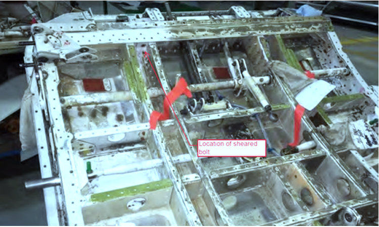
Fig 2: Door showing broken bolt location
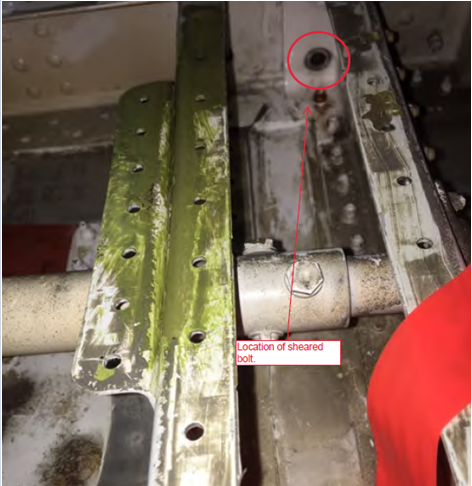
Fig 3: Close view showing bolt location
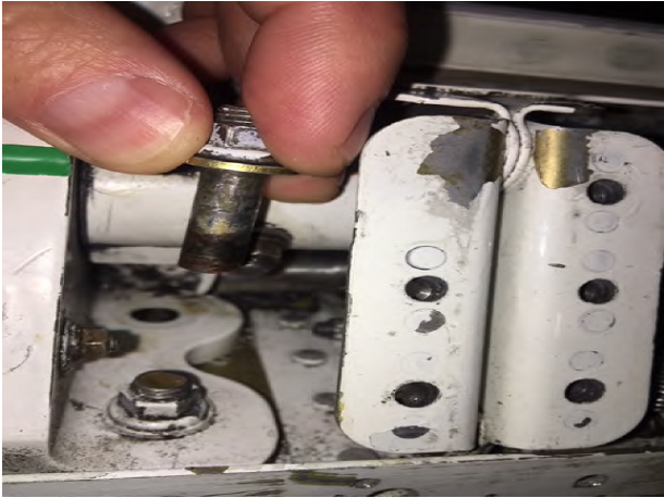
Fig 4: Broken bolt location back side
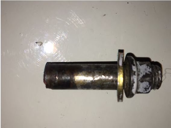
Fig 5: Broken bolt showing corrosion

Fig 6: Cracked fitting – front side

Fig 7: Cracked fitting back shows cracked right through
PIAGGIO
P180 Avanti II - Loose Jam Nuts on Rudder Trim Actuator
SDR #: 20160113002
Subject:
During inspection, it was noticed that the rod end jam nuts were not secure on the rudder trim actuator.
Transport Canada Comments:
After consultation with the service difficulty report (SDR) submitter, Transport Canada Civil Aviation (TCCA) understood that the area was inspected in accordance with Service Bulletin (SB) 80-0444. No other occurrences have been reported to TCCA. Operators and maintainers of these aircraft are reminded, that whenever performing maintenance in this area, to remain vigilant and observant for this reported condition. If the condition of loose jam nuts is found, please submit an SDR accordingly.

Rudder trim actuator loose jam nuts
PILATUS
PC12 45 - PC 12 Main Landing Gear (MLG) Fracture and Collapse
SDR #: 20220922013
Subject:
The MLG lower trailing link broke away from the upper yoke fitting. The pivot pin attach lug on the yoke fitting, inboard side, broke in half, allowing the lower trailing link bushing and pin to separate from the upper gear leg.
Transport Canada Comments:
This Feedback Article aims to raise awareness in the PC 12 community of potential undetected corrosion being present under specific bushings of the yoke fitting assembly. It is suspected that this corrosion weakens the bore in the yoke fitting which can cause the separation of the lug from the rest of the yoke assembly. This specific aircraft was positioning for takeoff at the end of the runway when the lower trailing link broke away. The gear assembly is presently with Pilatus in a Swiss lab for investigation.
Pilatus specifies in their MLG Component Maintenance Manual (CMM) that up to “25,000 flying hours or 30,000 landings (whichever comes first), the overhaul of the MLG is done 'on condition' and requires the disassembly, cleaning, check, repair (if necessary) and assembly of the component”. The overhaul consists of an examination and dimensional check of the bushings, but removal is optional.
Transport Canada Civil Aviation recommends that operators pay extra attention to these bushings during all routine maintenance checks for signs of corrosion. The Pilatus MLG CMM provides specific instructions for the subject bushings' removal, inspection, repair and reinstallation.

Picture 1 – Fractured gear impacting the runway

Picture 2 – Close-up of the lug with corrosion present in the bore

Picture 3 – CMM reference
PC12 47E - Pilatus PC 12 – Loose Anchor Nut – Rudder Hinge Attachment Bolt
SDR #: 20220819005
Subject:
During a maintenance check, the rudder was removed to inspect for play at the hinge point, and a Structural Repair Manual (SRM) repair was carried out by installing a bushing. During the rudder re-installation, when mounting the top rudder attach point bolt, a rattling noise was heard of something that had dislodged and fallen inside the rudder. Upon further investigation, it was noted that the anchor nut to which the bolt must be attached had fallen inside the rudder. After the anchor nut was retrieved, it was noted that the anchor nut was still riveted to the broken piece of rudder rib 6.
Transport Canada Comments:
The SRM repair mentioned by the submitter is Rudder Upper Hinge Fitting Repair RM06299 (Installation of an aluminum bushing). This repair has the operator increasing the top bolt hole to a larger size to accommodate a bushing, adding strength and preventing play-inducing wear.
Pilatus offers another repair, Rudder Upper Hinge Attachment Repair RM05387 (Replacement of the nutplate with a self-locking nut and washer). This repair replaces the anchor nut with a self-locking nut and washer. This repair also adds an inspection panel to access the lower portion of rudder rib 6.
Play in the rudder attachment fittings is checked while performing Pilatus Task: Rudder Inspection Check - 12-B-55-40-00-00A-313A-A. Operators are asked to keep this defect discovery in mind when finding play in the rudder upper hinge fittings of PC-12 aircraft.

Picture 1 – Illustrated Parts Cataloge (IPC) reference of rudder rib 6 and anchor

Picture 2 – Underside of rudder rib 6 with missing anchor nut

Picture 3 – Anchor nut with piece of rudder rib 6 still attached
PC12 47E Shocking Fuel Leak
SDR #: 20210707006
Subject:
The pilot discovered significant fuel leakage from the belly of the aircraft, inboard of the left-hand (L/H) wheel well area, while the aircraft was shut down on the ramp after a call. Upon investigation by maintenance, it was noted that a main fuel line had a small pinhole in it, causing a steady stream of fuel to jettison the aircraft. In the area of the puncture was a wire bundle that appeared to be chafed. It appeared that the wire chafed a hole in the fuel line, and the fuel was spraying onto the chafed electrical wires. The fuel spill was contained on the ramp, and the leaking fuel line was contained using temporary means to prevent further fuel loss on the ramp.
Transport Canada Comments:
The operator provided the following additional information:
A hole was found in the L/H wing fuel line part number (P/N) 528.24.12.173A caused by a chafing wire from the belly beacon P/N L78B18/l79A18N, which chafed through the insulation, exposing the bare wire, and had arced on the fuel line, causing the leak. The wire was able to chafe due to a rotated Adel clamp and standoff, which held the two beacon wires.
The aircraft was defuelled, the fuel line was removed, the wire was repaired with Raychem in accordance with standard practices, silicon fusion tape was applied to the hydraulic line, which the Adel clamp was attached to, and the Adel clamp was attached/reinstalled on the tape and positioned away from all lines. The Adel clamp cannot rotate due to friction from silicon tape. A new fuel line P/N 528.24.12.173B was then installed in accordance with standard practices.
The aircraft was refuelled, and the line was pressure tested with the boost pump. The engine run was completed; no further faults were found, and the aircraft returned to service.
This operator was fortunate that this difficulty did not progress into something much worse. A fleet campaign was initiated to inspect for proper clamp and wire position to ensure for necessary clearance between the two wires and fuel lines. No further findings were reported.
Clearance must be maintained between wires and adjacent components and structures. Please be vigilant for these types of dormant failures.

Picture 1 – Fuel stream from the chafe on the fuel line

Picture 2 – Chafe found on the fuel line
PC12 45 - No Steering Leads to Surprising Discovery
SDR #: 20191227003
Subject:
The flight crew of the subject aircraft reported that they lost all rudder steering control during ground taxi maneuvers. An investigation was performed and found that the forward rudder bellcrank part number 527.20.12.116 was cracked in half. The cracked bellcrank resulted in loss of steering and rudder control. The cracked bellcrank as well as a damaged rod end was replaced. A full rigging and control check was completed to return the aircraft to service.
Transport Canada Comments:
The flight crew of this aircraft was fortunate that the bellcrank failed during taxi and not in the air. Inspection by maintenance found that the bellcrank did not appear over-stressed or bent. The aft flange of the cracked portion seemed to have distorted as the bellcrank was in the final stage of failing. Black residue in the area of the forward cracked pieces was also noted.
After removal, the failed bellcrank was sent to Pilatus headquarters in Stans Switzerland for failure analysis. Preliminary findings point to a very small corrosion spot as the starting point of the crack/fracture.
The subject aircraft at 29 959 hours air time is of particular importance as it has been running on an airframe life extension program since nearly 10 000 hours air time.
At this time, Transport Canada does not recommend operators modify their maintenance schedule as the investigation by Pilatus is ongoing.

Pic. 1 Bellcrank assembly as found by maintenance prior to removal. Broken piece of bellcrank (circled) found on floor of cavity.

Pic. 2 Bellcrank removed on bench. Crack evident.
SW, PC12 45 - Steering System Troubles
SDR #: 20190408007
Subject:
Minor edits have been made to the text below taken from the Service Difficulty Report’s Problem Description. Transport Canada Civil Aviation reserves the right to edit for spelling, grammar and punctuation to increase comprehension.
While taxiing out from the hangar, the crew heard a loud bang as they were turning right. The right-hand rudder pedal went to the floor and the aircraft was unable to turn right without the use of brakes, however it was able to turn left.
The crew shutdown and the aircraft was towed back to the hangar. Upon inspection, it was discovered that the steering bolt that attached the fork bearing to the fuselage mounting bracket had sheared off.
The steering bolt, fork bearing, bracket and attachment bracket were replaced and new hardware installed. Aircraft returned to service with no further faults found.
Transport Canada Comments:
The crew of this aircraft was fortunate that the component bolt failed on the ground and not while in-flight. Pilatus has no lubrication schedule set for this bolt but has set a 600hr inspection interval for the steering components.
This submission is an excellent example of a Service Difficulty Report (SDR).
From the Canadian Aviation Regulations (CARs) Part 1, Subsection 1, Interpretation 101.01:
Service difficulty means a failure or malfunction of, or defect in, an aeronautical product;
Reportable service difficulty means a service difficulty that affects or that, if not corrected, is likely to affect the safety of an aircraft, its occupants or any other person
Please consult the CARs Part 5 Division IX for reporting requirements and timelines. You may also reference Advisory Circular (AC) 521-009 available as a link on Web Service Difficulty Reporting System (WSDRS). The AC is an excellent tool for guidance on SDR submission.

Pic 1: Sheared bolt in assembly

Pic 2: Sheared bolt
SW, PC12 47E - Improper Wiring Practices
SDR #: 20190329033
Subject:
Minor edits have been made to the text below taken from the Service Difficulty Report’s Problem Description. Transport Canada Civil Aviation reserves the right to edit for spelling, grammar and punctuation to increase comprehension.
During a routine inspection of the windshield heat wiring and splice crimps, it was noted that the left-hand pilot windshield wires were crimped improperly. This is what this inspection was designed to look for, after finding some windshields that were installed improperly. The two separate splice crimps were found to have been crimped backwards.
Transport Canada Comments:
This special inspection proved its worth. Sometimes routine maintenance can seem mundane and uninteresting. This particular maintenance staff was able to find the exact issue the inspection was calling out. Following procedure and being attentive during inspections can save a crew from an inflight failure.

1 - Improperly spliced wiring

2 - Properly spliced wiring
SW, PC 12 47E - Landing Gear - Electrical
SDR # 20170928006
Subject:
A pilot reported just before landing, a yellow advisory message "air/ground fail" and "RH weight on wheel fault". Upon inspection of the right hand (RH) weight on wheels switch, the cannon plug was found to be severely corroded and disintegrated into multiple pieces when trying to remove it. This cannon plug was covered by heat shrink, well-sealed at both ends and showed no sign of any faults from an external visual inspection.
Transport Canada Comments:
This is a good reminder about landing gear electrical components and the effects that our Canadian climate can impose on them. Extra care should be taken when inspecting this area of the aircraft. If necessary, remove heat shrink and coverings to get a closer look.

Corroded pieces of cannon plug back shell.
SW, PC 12 47E - Ailerons freezing in flight
SDR # 20150624001
Subject:
After the airplane departed the airport, the pilot did a normal climb to 28,000 feet. At approximately 1425Z a caution message appeared stating, “AP HOLD LH WING DN”. The Pilot disengaged the autopilot and found that the ailerons were locked in the neutral position. A lower altitude was requested as we’ll as a return to the departure airport. A descent was started at 1429Z and while going through approximately 18,000 feet, the pilot started getting some feel back from the ailerons. At 1443Z the pilot leveled off at 15,000 feet and although it could not be assumed that the ailerons were fully serviceable, a good response was received. With the return of some aileron control, the pilot then requested 15000 feet altitude, did an approach without any problems and landed at 1549Z. The weather conditions at 28,000 feet were clear sky, out of clouds with a temperature of -46 Celsius. The temperature at 15,000 feet was -19 Celsius.
The maintenance actions and findings were as follows:
The left and right aileron access panels were removed (Ref: IPC 57-60-00-010-941a-a Item 15 and Item 20) for access to inspect the aileron bell cranks (Ref: IPC 27-10-00-080-941a-a Item 145 and Item 150). The aileron control wheel was then actuated while observing the bell cranks. Maintenance noticed on the left aileron bell crank that the bearing (Ref: IPC 27-10-00-080-941a-a Item 180) was not rotating and the aileron drive arm pin (Ref: IPC l57-60-00-020-941a-a Item 210) was rotating inside the bearing. There was also water clearly visible and bubbling out of the contact surface between the bearing and the pin. Both aileron bell cranks were then removed and wear marks were found on the drive arm pins inside the aileron bell crank bearings. A complete assembly was later installed in freezer, sprayed with water and was found frozen solid after 30 minutes. A report was sent to Pilatus and an investigation is in progress.
Transport Canada Comments:
The temperatures on the ground at the time of this event would have been above freezing. No mention was made if the aircraft had been washed or if it had been left out in the rain. Water will turn to ice as aircraft climb into colder temperatures at altitude. Care must always be exercised to ensure that aircraft systems such as aileron controls are not left wet prior to flight. In this situation, water had made its way into the bell crank bearing; it could have been external water or condensation that built up over time.
Many manufacturers use sealed bearing assemblies with no prescribed lubrication interval. Depending on the aircraft’s operating environment, operators should be aware that they may need to go over and above what the manufacturer recommends. The use of manufacturer approved moisture displacing lubricants is a great way to prevent this type of occurrence. (Maintainers must always use only manufacturers’ recommended products as listed in the approved publications)

Aileron bellcrank arm bearing with obvious signs of advanced wear and failure
PIPER
PA30 - Push-Pull Cable Seizure Leading to Gear Collapse
SDR #: 20010523017
Subject:
The landing gear failed to retract on climb out and breakers popped. The gear failed to extend when the breaker reset and selected down, and there was no green light to indicate that the gear was down and locked. The pilot could not release the emergency gear extension handle. The right-hand gear collapsed on roll out. The teleflex cables were found to be very stiff in conduit/sleeve.
Transport Canada Comments:
TCCA has recently received information about a similar incident involving another Piper PA 30 aircraft, wherein the landing gear collapsed, resulting in significant damage to the aircraft. Positive gear retraction/extension can be problematic when push-pull (conduit) cable function has been degraded, or otherwise described as stiff. The cable assembly is an integral part of the normal extension/retraction and emergency gear extension system. Degraded function of this cable may negatively affect any emergency gear extension.
Warning signs that may indicate a stiff push-pull cable include:
- Circuit breaker trip during operation;
- High electrical load;
- Gear extends slowly, especially in cold weather;
- Gear motor unusually warm/electrical odour present.
FAA published AD 77-13-21 related to Piper Service Letter (SL) 782A, and Special Airworthiness Information Bulletin (SAIB) CE-08-50 which promotes the importance of SL 782B. TCCA discussed this topic in Feedback issue 2010/3 without noting the related FAA AD. Owners, operators and maintenance personnel should pay particular attention to the published recommended maintenance practices and subject matter of SAIB CE-08-50, and continue to complete the reoccurring requirements of AD 77-13-21.
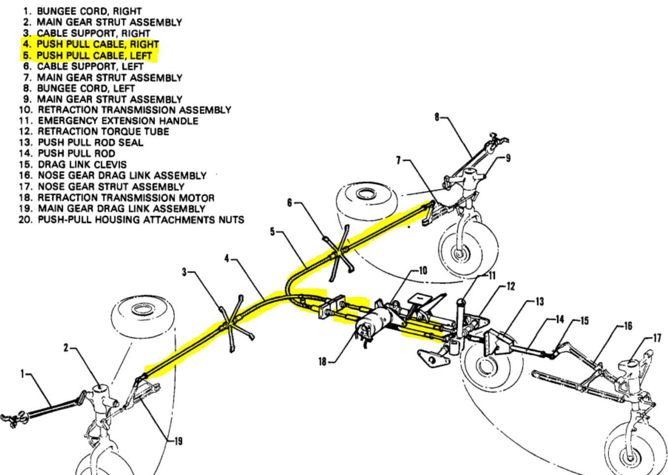
Picture 1 – Left, Right Push-Pull Cable
Picture 1 - Text in the picture
Bungee cord, right
Main gear strut assembly
Cable support, right
Push pull cable, right
Push pull cable, left
Cable support, left
Main gear strut assembly
Bungee cord, left
Main gear strut assembly
Retraction transmission assembly
Emergency extension handle
Retraction torque tube
Push pull rod seal
Push pull rod
Drag link clevis
Nose gear drag link assembly
Nose gear strut assembly
Retraction transmission motor
Main gear drag link assembly
Push-pull housing attachments nuts
PA44 180 - Main Landing Gear (MLG) Strut Assembly – Fork and Piston
SDR #: 20210803019
Subject:
During an inspection of the gear down-lock switch on the right-hand (R/H) MLG, an aircraft maintenance engineer (AME) found, by chance, a crack on the lower strut assembly inboard of the axle, where the brake torque plate bolts attach. The crack is slightly above the bolt at the 1 o’clock position, and it is where the strut joins the axle. The location of the crack is in a significant load bearing area.
Transport Canada Comments:
Piper Aircraft published service letter (SL) 1263 due to MLG piston tube fatigue cracking. Shortly thereafter, an accident (National Transport Safety Board report WPR21LA117) involving the separation of a R/H MLG occurred. The root cause was identified as failure of the landing gear strut piston tube due to fatigue cracking from corrosion pitting.
It was noted in a subsequent Service Difficulty Report (SDR) 20210806009, that Piper has produced a replacement strut assembly, part number (P/N) 67037-006 (also referenced in the above SL), which appears to have a notable design improvement in the affected area of the lower fork.
Transport Canada Civil Aviation (TCCA) recommends compliance with SL 1263. Additionally, paying special attention to the area of the fork identified in this SDR is also recommended. High cycle aircraft, such as those used in a flight training role, may be particularly susceptible.

Figure 1 – Strut assembly fork – Crack location
PA44 180 - Nose Landing Gear Centering Spring Bracket Installed Upside Down
SDR #: 20220822023
Subject:
The pilot was practicing slow flight and noticed that when the landing gear extended, only the main lights illuminated. He made several attempts to deploy the landing gear with no success in getting the nose gear extended. The pilot flew by the tower, which confirmed that the nose landing gear was not fully extended. Only a small portion of the tire could be seen in the wheel well. The pilot elected to burn some fuel for an hour and then land. The aircraft landed and came to rest on its nose nacelle. The pilot feathered the engines on landing. Unfortunately, the propellers struck the ground, bending back the blade tips.
Upon inspection by maintenance, it was found that the centering spring (shimmy damper) bracket was installed incorrectly, which caused the nose gear to be turned off centre, and, consequently, the gear got stuck in the wheel well. Before this flight, there was a ground handling incident where the centering spring bracket had been bent. The bracket was removed, straightened, inspected, and reinstalled. It was at this time that the bracket was reinstalled upside down, causing the nose gear to spring off centre with weight off the wheel.
Transport Canada Comments:
Owners, operators, and maintainers are reminded to always follow the appropriate instructions for continued airworthiness (ICA). In cases where clarity of assembly cannot be positively ascertained, the type certificate holder should be contacted for assistance.
Although the outcome of this occurrence was likely burdensome on many levels, it was not catastrophic. Service Difficulty Reports (SDRs) should continue to be submitted for occurrences related to assembly / installation lack of clarity. The potential for mistakes and resultant consequences are not always apparent while completing complex tasks, especially if these tasks are new to the Aircraft Maintenance Engineer.

Figure 1 – Correct orientation of centering spring bracket

Figure 2 – Incorrect orientation of centering spring bracket
PA23 250 - Fuel Selector Valve Control Cable Failure at Swivel Fitting
SDR #: 20220411027
Subject:
Engine surging and loss of power due to a fuel supply problem.
Transport Canada Comments:
The engine power loss occurred during flight in the right-hand engine when the pilot selected the inboard fuel tank, as the outboard fuel tank capacity had been exhausted. An emergency was declared with the intention to land as soon as possible. While troubleshooting, the electric boost pump was turned on with no effect. The pilot utilized the fuel cross-feed system from the left-hand engine, which provided fuel supply and returned the right-hand engine power back to normal. The aircraft landed safely shortly thereafter.
The Federal Aviation Administration (FAA), the State of Design for the product, published Airworthiness Directive (AD) 80-18-10, which requires inspection of all fuel selector valve control cables using 10x power magnification each 100 hours. Piper Service Bulletin No. 507 has been referenced within the AD for specific inspection locations, highlighting all swivel fittings.
Although the fuel selector valve control cable had been recently inspected prior to the incident, the defect was not uncovered at that time. The fuel selector valve control cable inner wire fractured under the crimping cup of the swivel fitting.
It is important to remain vigilant and avoid complacency when completing all maintenance, with special attention to the requirements of an AD.

Figure 1 – Broken fuel selector valve control cable inner wire

Figure 2 – Location of failure within pedestal

Figure 3 – Fracture located at swivel fitting connection
PA28 161 - Main Landing Gear Stub Axle Lug Cracked
SDR #: 20160315001
Subject:
The right-hand main landing gear was found cracked at the torque link lower attachment point on the stub axle and oleo piston assembly during routine maintenance. The crack was found by visual inspection and was approximately three-quarters of the way through the attachment point, outboard boss. The lower attachment point is not affected by Piper Service Bulletin (SB) 1131A, or SB 1179. Each of these inspections are looking for cracks at the upper torque link attachment point. Federal Aviation Administration (FAA) Airworthiness Directive 67-20-04 and Piper SB 248 require inspection of the torque link and not the lower attachment point. The stub axle and oleo piston assembly were replaced, and the aircraft was returned to service.
Transport Canada Comments:
The Service Difficulty Report (SDR) submitter is correct, Piper SB 1131A and SB 1179 both focus on the upper torque link attachment point. For Piper PA-28 and PA-32 series aircraft that operate in a flight-training role, experiencing hard landings, or where many takeoff and landing operations are performed routinely, it is recommended to pay special attention to the lower stub axle lug as a possible failure point.
A cracked stub axle lug may be partially hidden from view by the inner wheel half when installed. The use of a 10x power magnifying glass, as described in Chapter 32 of the Maintenance Manual, to visually inspect the radii may assist in identifying a cracked stub axle lug. Transport Canada Civil Aviation (TCCA) encourages owners, operators, and maintainers to continue reporting any defects noted.

Inner radius of stub axle lug
PA23-250 - Piper Aztec Emergency Exit Window Assembly
SDR #: 20210302019
Subject:
The emergency exit window assembly departed inflight.
Transport Canada Comments:
The occurrence aircraft had undergone maintenance just prior to the incident flight. It was determined that the emergency exit window assembly was not installed correctly, possibly due to a lack of clarity of the instructions in the maintenance manual (MM).
In addition to the above occurrence, there could be a link to an accident in 2019 where the emergency exit window assembly could not be opened. It was impossible to determine the exact cause of this failure, as the assembly was completely destroyed by the post-impact fire.
Link to Transportation Safety Board of Canada (TSB) Air transportation safety investigation report A19Q0091
“A post-impact fire broke out. Given that the fire was burning near the right wing, on the side where the main door was located, the pilot and the passenger-instructor went to the back of the aircraft with the intention of opening the emergency exit window on the left side, but they could not get it open. They were still able to evacuate the aircraft through this window because the plexiglass had been shattered on impact.”
Piper Aircraft completed a thorough review of the MM instructions relevant to the emergency exit window assembly used on the PA-23-250 model. The applicable MM, part number (P/N) 753-564 has been revised, dated 31 July 2021. This latest revision provides clear, detailed instructions for the removal and installation of the emergency exit window assembly.
Transport Canada Civil Aviation (TCCA) strongly suggests owners, operators and maintainers review and adopt the latest publication of Piper Aztec MM P/N 753-564.
")
Picture 1 – Side view of the Piper PA-23-250 aircraft showing the emergency exit window (Source: TSB A19Q0091)
")
Picture 2 – Emergency exit window removed (Source: TSB A19Q0091)
PA44-180 - Throttle Cable Stuck at Cruise Setting
SDR #: 20200915012
Subject:
During a routine training flight, the pilots found that the right throttle was stuck at the cruise setting. The right engine was shut down on final approach and the propeller feathered, and the landing was made with just the left engine operating. Maintenance inspected the throttle control at both ends and found no obvious faults. The control had been replaced in February 2019 and had about 500 hours air time in service. The engine end of the control was removed and the rubber boots slid back, and then it was discovered that the two (2) segments of the control end were stuck together. Lubricant was applied to the joint of the two (2) segments to free up the control until it worked normally again. This aircraft had sat unused for about four (4) months during the COVID-19 shutdown.
Transport Canada Comments:
A detailed search of service difficulty report (SDR) data indicates PA44-180 throttle control cables part number (P/N) 554-321, 554-528 and 554-546 (P/N 554-321 also installed on PA34-200/-200T/-220T) continue to experience various defects described as bind, break, frayed, froze, seized, separated, stiff, etc. The trend does not indicate an increase in reports, but as the submitter above experienced, additional circumstances could play a role in an undesirable outcome. Piper has published service bulletin (SB) 1220C - throttle cable seizing applicable to a specific serial number range but not inclusive of all PA44-180 aircraft. Transport Canada Civil Aviation suggests that owners, operators and maintainers pay particular attention to the throttle control system on all PA44-180 and PA34-200/-200T/-220T aircraft, and continue to report any service difficulties experienced.
PA31 350 - Gear up Landing due to Broken Hydraulic Line Flare
SDR # 20190506013
Subject:
The landing gear would not extent in flight. The pilots tried pumping the gear down using the emergency gear pump. There was no response. The pilots were forced to make a gear up landing on the runway.
Upon inspecting the aircraft during the recovery from the runway, there was hydraulic fluid leaking from the aircraft. An aluminum hydraulic line was found broken at the flare. Once the line broke, the hydraulic pumps expelled the fluid from the reservoir down to the top of the normal system standpipe. The rest of the fluid was expelled by the pilot while operating the emergency system.
Once the aircraft was lifted with a crane and placed on jacks, the broken aluminum line was replaced with a flex line temporarily and the system serviced with fluid. The emergency gear pump was actuated and the gear extended immediately. The powerpack was replaced 42.9 hours and 47 cycles prior to the incident, and no hydraulic leaks were noted during this time.
Transport Canada Comments:
Piper PA31 gear up landing events have occurred on at least 3 occasions due to a cracked hydraulic line flare at the powerpack. A failed line in the hydraulic system can allow all the fluid from the hydraulic reservoir, including that portion contained in the power pack emergency sump, to drain out.
Operators and maintenance personnel are reminded that improper alignment, clamping and torqueing of hydraulic lines and fittings can lead to torsional or bending pre-loads, and introduce fatigue cracking.

Hydraulic door open tube assembly failure at flare
PA-28-140 - Control Column T Section Welds Cracking and Failures
SDR #: 20170331002
Subject:
Note: Original text of submission has been edited to remove identifiable information and for improved reading.
Further to Civil Aviation Safety Alert (CASA) no. 2016-14, we removed the tee-bar control column (part number 62703-33) from our 1969 Piper Cherokee PA-28-140.
We carried out a Magnetic Particle Inspection (MPI) of the tee-bar and the MPI identified "an indication [of a possible crack] along the edge of the weld at a length of approximately 1.9 cm” which may be under-cutting from the original weld. Regardless, it showed up as an indication and may be a stress riser.”
Transport Canada Comments:
Transport Canada Civil Aviation (TCCA) published CASA 2016-19 on December 19th 2016 following an incident involving a PA-28-140 aeroplane. The aircraft’s control column T section weld at the junction of the horizontal and vertical tubes failed while a pilot instructor was attempting to land the aircraft. The horizontal tube severed from the vertical tube, resulting in sluggish and delayed flight control response. Luckily, the aircraft was very close to the runway and the instructor landed the aeroplane safely.
When the operator of the incident aeroplane attempted to replace the failed control column with a used serviceable unit from an out of service aeroplane, it carried out an MPI and found the replacement column to be cracked as well. At the relevant time, the aforementioned control columns were the only known reported instances of these types of failures in the long history of the Piper PA-28 fleet. The circumstances of this new event however are very similar. All three aeroplanes were high time PA-28-140 models. This SDR reports that the latest aeroplane has accumulated over 11,000 hours in service.
As an interim measure until such time as Piper Aircraft has concluded its investigation into the control column failures and the FAA makes a determination of what action, if any, will be undertaken in response to the previous two events, TCCA published CASA 2016-14 to alert owners and operators of the issue. The CASA recommends an immediate detailed visual inspection of the control column T section welds for anomalies and further recommends the removal and MPI of the control column at the next annual or 100 hours inspection.
In this particular instance, due to age and time in service of its aeroplane, the operator exercised caution and due diligence by electing to remove the control column to carry out the MPI even though the aeroplane was not yet due for its annual inspection.
TCCA reminds all owners and operators of the PA-28 series aeroplanes to carefully consider the age and condition of their aeroplane with respect to following the recommendations contained in CASA 2016-14. The CASA can be found at the following link:
https://tc.canada.ca/en/aviation/reference-centre/civil-aviation-safety-alerts/piper-pa-28-control-column-tee-bar-assembly-cracking-failure-civil-aviation-safety-alerts-casa-no-2016-14.
TCCA reminds commercial air operators, flight training unit operators and approved maintenance organizations of the regulatory requirements to file an SDR where any reportable service difficulties are found during a visual or MPI or any other maintenance activity. In addition, while not a regulatory requirement, TCCA highly recommends that individual aircraft owners and maintainers should file an SDR if any anomalies are found. TCCA uses the intelligence and evidence gathered from the WSDRS database to assist in making a fact based determination as to whether an unsafe condition exists in the fleet and or whether mandatory corrective action by the FAA or TCCA is necessary.

Control Column Assembly
SAAB
340B - Nose Wheel Bearing Failure
SDR #: 20220615008
Subject:
The pilot conducted a scheduled flight. During regular rollout, the pilot felt an unusual and violent vibration from the nose landing gear upon rotation. As the gear retracted, the noise and vibration went away and the takeoff carried on as usual. The pilot called the tower to check the runway to see if there was a possibility that the nose wheel might have fallen off. A few minutes later, the tower confirmed that they found a wheel. The pilot continued the flight, declared an emergency with the air traffic control centre and advised that he would be conducting an emergency landing. The pilot requested a low pass to get a detailed description of the integrity of the landing gear. The tower confirmed that the right front wheel was missing, and the left front wheel was still in place. The pilot conducted an emergency landing. The maintenance crew inspected the nose landing gear and found that the nose wheel assembly bearing mount was still on the nose landing gear axle. The nose wheel axle was damaged. Upon inspecting the nose wheel bearing, it was suspected to be inadequately greased, causing bearing failure.
Transport Canada Comments:
There have been a number of wheel bearing failures on a number of different aircraft models. Maintenance personnel are advised to ensure that wheel bearings are properly greased and torqued to specifications published by the manufacturer.

Axle with the remainder of the wheel bearings after the wheel departed the aircraft on takeoff